Show Me How
to do things
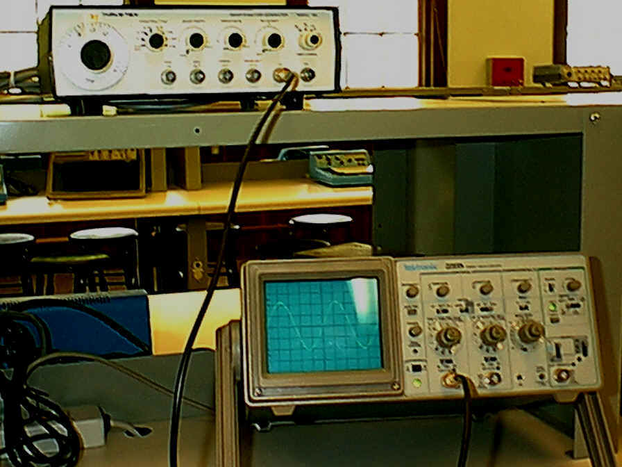
Connecting a 1kHz signal to Ch 1 of the Oscilloscope.
Turn Generator on,
adjust Frequency Adjust to 1.0,
set Frequency Multiplier to 1K,
select Sign wave output,
adjust Amplitude to mid value and
connect coax cable to Low output
Turn Oscilloscope on,
connect coax from Generator to Channel 1 or Channel 2 input, (below I will
assume CH 1)
put AC GND DC switch
to AC
put Trigger Mode
switch to Auto,
put Trigger Source switch
to CH1,
put Mode switch (above
input controls) to CH1,
adjust Position so trace is in middle of screen,
adjust three Cal knobs fully clockwise,
adjust VOLTS/DIV so the signal
fills the screen,
adjust SEC/DIV to display
one to two cycles on the screen
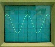
Measure the amplitude of a signal with an Oscilloscope.
Make sure the Cal knob is fully clockwise for the input channel you are using.
Adjust the Volts/Div knob so waveform fills as much of the screen as possible but not going outside (above or below) the display. We use the largest waveform to obtain the maximum accuracy of the measurement. Since the accuracy is about 0.1 divisions, a signal that is 4 divisions high has a 2.5% accuracy. If the signal is 1 division high the accuracy is only 10%.
Adjust the bottom of the waveform to be on one of the solid gradicule lines.
Count the number of divisions from the bottom to the top of the signal. (The example below is 4.1 divisions.)
Multiply the # of divisions by the Volts/Div setting on that control. (For example: 0.5 V/DIV * 4.1 Div = 2.05 VPP (volts peak to peak))
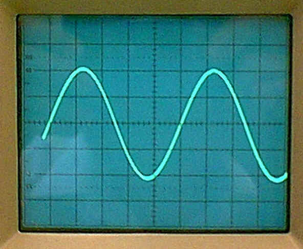
Measure the Period of a signal with an Oscilloscope.
Make sure the Cal knob is fully clockwise for the input channel you are using.
Adjust the SEC/DIV control till there is one complete cycle displayed but as few as possible and still have one.
Adjust the horizontal position so that the signal crosses the zero axis on a solid vertical line.
Count the number of number of horizontal divisions for one complete cycle. ( The example below is 5.1 divisions).
Multiply the # of divisions by the SEC/DIV setting. (For example 0.2ms/DIV * 5.1 DIV = 1.02 ms)
Calculate the Frequency of a signal.
Frequency is defined as cycles per second and has the units of hertz (Hz). The period of a signal defined as the time per cycle. Therefore:
frequency = 1/period
In the example above: 1/1.02ms = 980Hz.
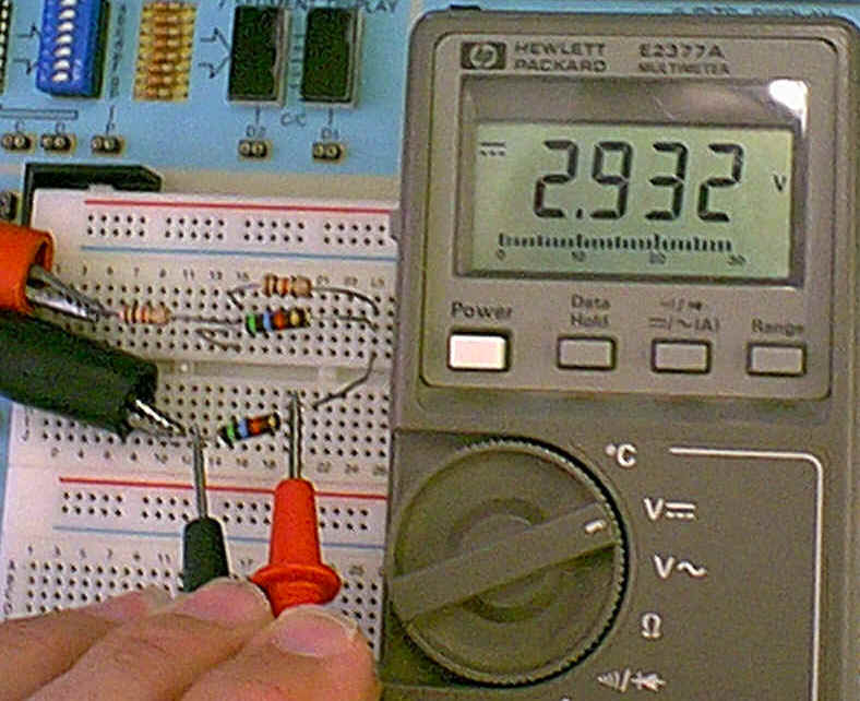
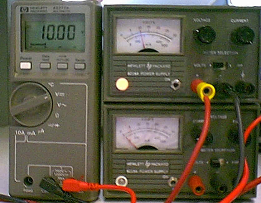
Measuring Power Supply voltage.
Set the meter selector switch to DC Volts and turn the power on.
Connect the red and black leads to the + and - terminals of the power supply.
Turn the power supply on.
On the power supply adjust the Voltage control for the desired (10 volts here) voltage on the meter. The meter on the Power Supply should read close to the same, but it is not as accurate as the digital multimeter.
To measure voltage across a resistor, hold the meter probes on either side of the resistor. The meter below is indicating 2.93 V across the 5.6 K resistor. Note also the right side of the resistor is positive.
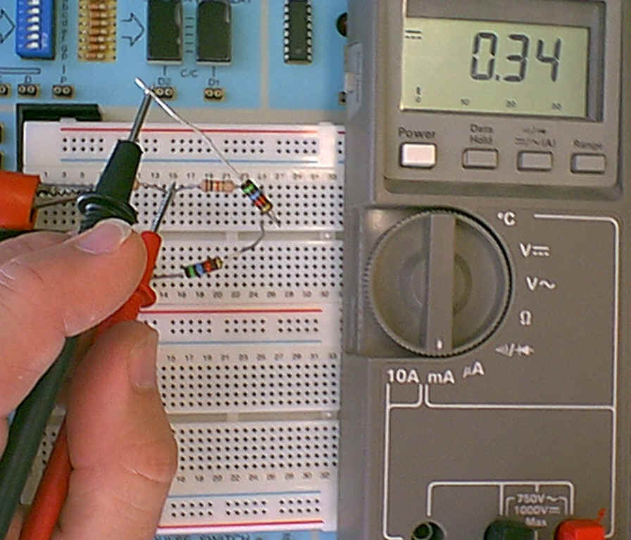
To measure current:
the meter selector switch must be set to the µA, mA or 10A scale
the circuit must be "opened" and the meter inserted into the circuit. Below the meter is measuring the current through the 5.6K ohm resistor and reading 0.34 mA or 340 µA.
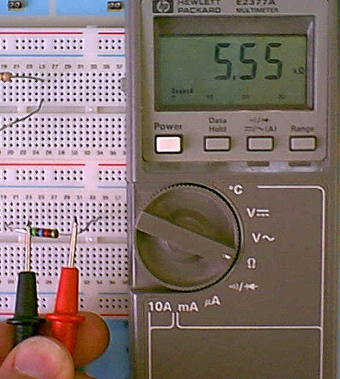
To measure a resistor:
Remove the resistor from the circuit.
Turn the Digital Meter on and set the selector switch to read resistance .
Touch one probe to each side of the resistor being careful not to touch the metal ends. (The resistance through your fingers can affect the measurement.) Below 5.55 K ohms is being measured.
To measure τ of a step response of a first order circuit:
adjust time base so there is at least one complete cycle on the screen (but make sure CAL knob is filly clockwise) (frequency of input square wave must be low enough to allow the signal to settle to (almost) its final value)
adjust the amplitude of the signal to be 4 divisions high (Adjust input level on oscilloscope.)
adjust horizontal position so signal starts to decay (or rise) on a vertical line (point 'a')
Vout at τ, is 0.368 Vin (0.368 is e-1). Therefore, we want to find the time it takes to reach 0.368 * 4 divisions or 1.5 divisions.
Measure the time from "a" to where the trace crosses the 1.5 division mark. In the figure above it is 0.5 divisions * 2ms/DIV = 1ms.
The rise time (tr) is defined as the time that is required for the voltage to go from 10% to 90% of the average amplitude. Similarly the fall time (tf) is the time required for the voltage to fall from 90% to 10% of the average amplitude. In the Figure above, the rise time (tr) is the time the signal takes to rise E divisions. Where E is the average amplitude of the pulse.
Therefore to measure the rise time:
Adjust the average input level for an amplitude of 5 divisions. With a second order step response, the average amplitude would be the amplitude the voltage settles to.
Make sure the Cal control in the center of the Time Base control is fully clockwise or in the calibrated position.
Adjust the time base so one to two cycles are displayed on the screen.
Switch the trigger slope switch to trigger on a negative slope so there is a positive slope displayed in the middle of the screen.
Since 10% of 5 divisions is 0.5 divisions, measure the rise time (tr) as the time the voltage takes to rise from 0.5 divisions to 4.5 divisions. To make this measurement easier, adjust the waveform up 1/2 a division. This way the 10% to 90% measurement will be an even 4 divisions.
Measure the number of horizontal divisions the signal takes to rise vertically the 4 divisions. The rise time is then: (# of divisions) * (SEC/DIV) on the time base control. If this time is less than 1/2 a division, change the magnification switch to x10. Again measure the number of divisions the signal takes to rise the 4 divisions. The rise time is now: (# of divisions) / (10) * (SEC/DIV).