Triggering: The SEC/DIV control sets how fast the the electron beam in the CRT will sweep across the screen, but there needs to be something that tells the beam to begin its sweep, this is the trigger. The sweeps are triggered by a point on an input signal called the trigger point. The trigger signal can be created by an internal frequency generator in the oscilloscope, the signals on channel 1 or channel 2 or both, or an external signal .
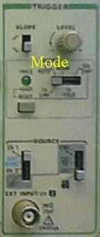
SLOPE: Selects the slope of the signal that triggers the sweep. If this control is in its up position then it is set to use a positive slope of a particular amplitude to trigger a sweep. When the control is in the down position it is looking for a negative slope.
LEVEL: Adjusts the trigger signal amplitude for the trigger point. When turned fully to the left the trigger will look for the lowest amplitude of the trigger signal to be used as the trigger point. When turned fully to the right the trigger will look for the highest amplitude of the trigger signal to be used as the trigger point.
MODE: The P-P AUTO and NORM settings are the only settings normally used. The other settings are for special uses of the oscilloscope like taking a "photograph" (one sweep) of an electrical phenomenon that exists for a short time etc. The P-P AUTO trigger mode will always display a trace regardless of any input signals because it uses an internal frequency generator in the oscilloscope. When viewing two signals (from CH 1 and CH 2) that should be synchronized (begin and end at the same time) they can appear unsynchronized by the nature of the P-P AUTO trigger. To confirm that synchronization exists you can use the NORM setting. NORM uses the signal from CH 1 or CH 2 or an external signal to trigger the sweep, therefore if the traces are synchronized they will appear as such, and if there is no signal on CH1 and CH2 then there will be no trace because nothing is triggering the sweep.
SOURCE: When in NORM mode you can set the trigger to begin its sweep according to a trigger point on the signal from CH 1 or CH 2 or an external (EXT) signal or from a combination of CH 1 and CH 2 using VERT MODE. VERT MODE and EXT are rarely used and probably won't be used in your course.
EXT INPUT: A BNC connector for an external input.