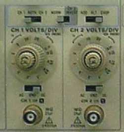
Mode: Both channel 1 (CH 1) and channel 2 (CH 2) can accept a voltage input signal. The mode selectors determine how those input signals are displayed on the oscilloscope's screen.
The leftmost mode selector reads "CH 1 BOTH CH 2". Set this to "CH1" if you want just the signal from channel 1 to be displayed. Set this to "CH 2" if you want just the signal from channel 2 to be displayed. Set this to "BOTH" if you want both the signal from channel 1 and channel 2 to be displayed together.
The central mode selector reads "NORM CH 2 INVERT". Set this to "NORM" if you want to see the signals from either or both of the channels as they are naturally. Set this to "CH 2 INVERT" if you want to see the signal from channel 2 inverted (vertically opposite of how it would be naturally).
The rightmost selector reads "ADD ALT CHOP". Set this to "ADD" to see the algebraic sum of the channel 1 and channel 2 signals. When you use "ADD", the CH 1 and CH 2 VOLTS/DIV should be set to the same value. Selecting "CH 2 INVERT" when "ADD" is selected causes the CH 2 waveform to be inverted. This allows you to see the algebraic difference between the CH 1 and CH 2 signals. When "BOTH" channels are selected, the display is time-shared (signals from both channels are displayed at the same time). The "CHOP" mode displays each channel for a short time and multiplexes (goes rapidly back and forth between the signals) during the sweep to give the appearance of displaying both channels at once. The "CHOP" mode works better than the "ALT" mode for sweep speeds slower than 1ms per division and for low-repetition-rate signals that make the display flicker (up to 2ms/division). The "ALT" mode displays each channel for the duration of a complete sweep. It gives a cleaner display of multiple channels than the "CHOP" mode does and is usually preferred at moderate to high sweep speeds (above 2ms/division).
CH 1 or CH 2 VOLTS/DIV: Firstly, you should understand what is meant by the CRT Graticule. Secondly, make sure the "CAL" knobs are turned fully clockwise as far as they will go; they should remain in this position for every measurement.
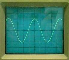
The CRT Graticule is divided into 80 divisions. Each division is a square. Along the lines that make up the sides of the square divisions are tick marks that further divide the line lengths into fifths.
In the upper left hand corner of the "VOLTS/DIV" knob is a area marked "1X". In the upper right corner there is an area marked "10X PROBE". Since you are probably not going to be using a probe, the latter area is not important. Therefore, the values you should be reading are in the "1X" area.
The voltage is indicated on the vertical axis. The range of your oscilloscope is 5mV/DIV (marked 5m) to 5V/DIV (marked 5). 5 volts per division (VOLTS/DIV) is exactly what it sounds like: the height of one square division on the CRT Graticule represents 5 volts from the signal input. This is true for both CH 1 and CH 2 and works the same way for any other volts per division value.
If when you hook up your signal from the device you are testing, nothing appears on the screen, then try playing with the "VOLTS/DIV" knob to get the signal in the proper range. The larger the display output is on the screen, the more accurate your measurements will be, so play around with the "VOLTS/DIV" knob until the signal being displayed is the largest it can be and still fit on the screen.
CH 1 or CH 2 AC GND DC Selectors: On channel 1 or channel 2 you can input two kinds of voltage signals: AC or DC. AC stands for "Alternating Current". It is a way of transferring electrical power where the electric current and voltage values' instantaneous value and direction change periodically (usually wavelike). DC stands for "Direct Current". It is a way of transferring electrical power where the electric current and voltage values' instantaneous value and direction are constant.
On the oscilloscope, AC is defined as it is above but DC refers to the input of a coupled (joined) signal that can have both AC and DC components. Think of water with a smooth surface level with your line of sight, now consider waves moving across that surface. We will call the original position of the surface the reference position. The crests of the waves are above the reference position and the troughs are below, by equal distances. These waves are like the waves of an AC signal. Now if you were to dive under the water and look up, the reference position would be above you. We will call this distance that the reference position is above you the "offset distance". You watch the waves continue to travel across the surface of the water, but it all takes place with respect to a reference position that is offset by the offset distance from you. This offset is like coupling (joining) a DC signal to the AC signal you were originally watching. The DC offset can move the reference position up if it is positive or down if it is negative. Setting the scope on DC will allow you to watch the the signal and the DC offset at the same time. Setting the scope on AC will allow you to only watch the AC component of the signal, which will vary with respect to a reference position at the ground level instead of varying around its true reference position at the DC offset level.
The GND position displays the ground level for the channel. A good practice is to set the selector to GND and then use the vertical position controls to adjust the ground level to a certain line on the CRT Graticule (usually the line in the middle of the screen). Make a note of that line and then switch to either AC or DC input. If you switch to DC input and the reference position for any AC signal being displayed is not at the ground level then it is easy to measure the DC offset since it is just the number of divisions between the ground level and the AC reference position multiplied by the VOLTS/DIV volts per division value for the channel.
BNC Connector: The metal plug at the bottom of the "VERTICAL" area of the oscilloscope dials area is the input BNC connector which usually accepts a coaxial cable. As indicated on the the scope, the input resistance is 1MW and the input capacitance is 25pF; and the total input voltage cannot exceed 400V (from the ground level to the highest peak of the signal).