Instrument Familiarization - Multimeters
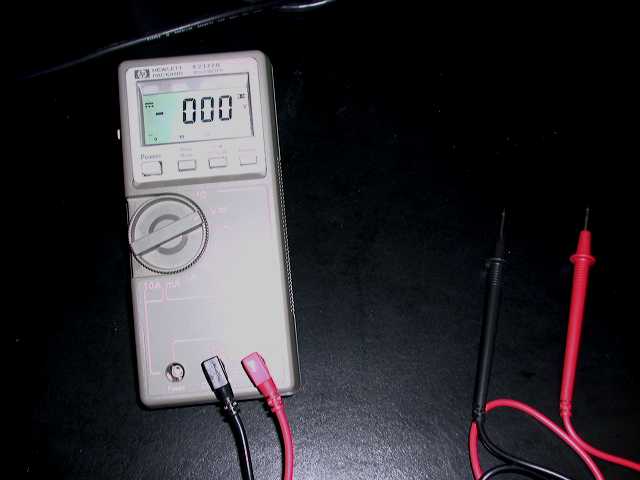
Ammeters measure current, voltmeters measure voltage and ohmmeters measure resistance. These devices are often combined into one instrument called a multimeter or VOM (volt-ohm-milliamp). This lab experiment is designed to familiarize oneself with a multimeter by measuring the three separate measurements of this device in a DC circuit. Measures of DC current and voltage are made with analog or digital meters. An analog meter has an indicating pointer whose angular deflection depends on the magnitude of the variable it is measuring. A digital meter displays a set of digits indicating the value of the measured variable. Digital multimeters are also referred to as DMMs (digital multimeters) To measure the voltage or current, a meter is connected to a circuit using terminals called probes which are colour coded to indicate the reference direction of the measured variable. Meter probes are colored red and black, for the positive and negative terminals respectively. A voltmeter measures the voltage across its terminals while an ammeter measures the current flowing through the terminals, usually in the direction of red to black. An ideal voltmeter is modeled by an open circuit, where the open circuit is replaced by a voltmeter and an ideal ammeter is modeled by a short circuit, where the short circuit is replaced by an ammeter. The Philips PM2503 is an analog meter and the HP E2377A is a digital meter and are the two types meters discussed in this lab but only the HP is used in the experiment.
Pre-Lab
1. Read through this document to familiarize yourself with the
equipment that you will be using in the lab.
2. Click on the following link. A word document will appear. Print out
the word document and bring it to the lab. Remember, if you come to the lab
without the printed document then you will have not completed your pre-lab
exercises, which will result in a loss of marks for this lab.
|
Purpose
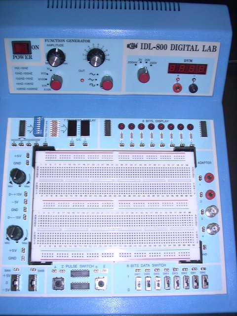
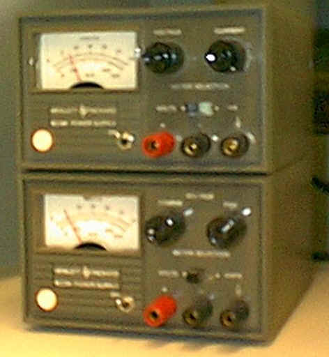
Equipment
|
|
Procedure
1. Set up the circuit with power supply as shown below. Show
me how
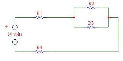
2. Check Voltage
Test the incoming voltage to be sure it is 10 V. If not, adjust
the voltage from the power supply until it reaches 10 V.
Show me how
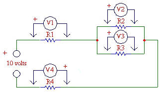
3. Voltage Measurements
Take the individual voltage readings across each resistor and enter
the values in the first column of Table 1. Show
me how
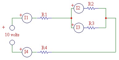
4. Current Measurements
Measure the individual current flow through each resistor and enter
values in the second column of the table. Show
me how
WARNING: METER MAY BE DAMAGED IF CONNECTED INCORRECTLY
5. Resistance Calculated
Calculate the resistance of each resistor using the measurements of
V and I using Ohm's Law (R = V/I). Enter values into the third column
of the table.
| 6. Resistance Measurements
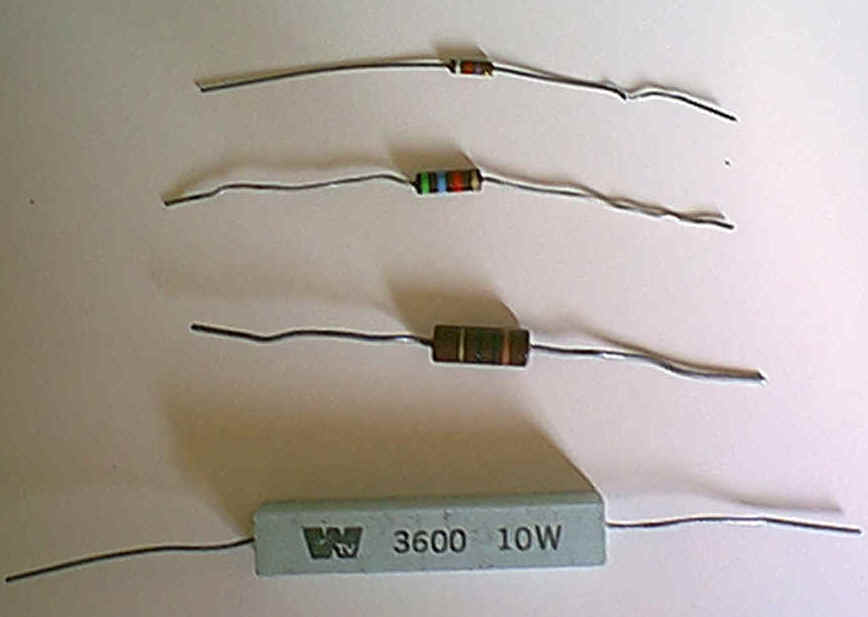
Measure the resistance of each resistor using the resistance function of the multimeter. Show me how. Take one resistor from the proto board at a time so as not to mix up the resistors. Enter the values in the fourth column of the table. 7. Indicated Resistance Value
|
|
Table 1. Data to be gathered for Lab 1.
|
|
|
|
|
|||
|
|
||||||
|
|
||||||
|
|
||||||
|
|
Results
1. From the information in the table, determine if the calculated and
measured values of the resistors are within the rated tolerance values. Why are
the calculated and measured values not exactly alike?
2. Compare the voltage readings across R2 and R3. Explain the relationship.
3. Compare the current flow through R1 and R4. Explain the relationship.
4. Calculate the actual tolerances of measured resistance and the calculated resistance of the resistors. Are they within their indicated tolerance? If not explain.
The following question pertain to information found in the operating manuals:
5. When measuring voltage, a meter will introduce a parallel resistance to the circuit being measured. The amount of this meter resistance is designated as the input impedance. Compare the Philips PM2503 analog meter and the HP E2377A digital meter when measuring a 50 mV DC voltage. State which meter would have a less detrimental effect on the circuit being measured.
6. What is the purpose of the hold button on the HP E2377A or the two hold buttons on the RadioShack meter?
7. What is the maximum current input that the Hewlett-Packard model
E2377A can accept when selected to either the microamp or milliamp range?